PDF Publication Title:
Text from PDF Page: 035
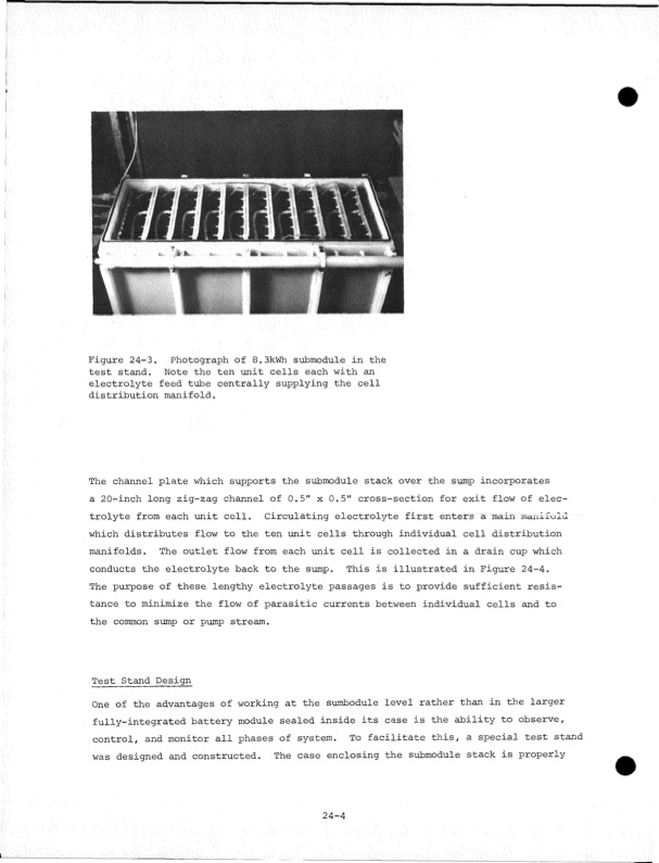
Figure 24-3. Photograph of 8.3kWh submodule in the test stand. Note the ten -unit cells each with an electrolyte feed tube centrally supplying the cell distribution manifold. The channel plate which supports the submodule stack over the sump incorporates a 20-inch long zig-zag channel of 0.5" x 0.5" cross-section for exit flow of elec trolyte from each unit cell. Circulating electrolyte first enters a main manifold which distributes flow to the ten unit cells through individual cell distribution manifolds. The outlet flow from each unit cell is collected in a drain cup which conducts the electrolyte back to the sump. This is illustrated in Figure 24-4. The purpose of these lengthy electrolyte passages is to provide sufficient resis tance to minimize the flow of parasitic currents between individual cells and to the common sump or pump stream. Test Stand Design One of the advantages of working at the sumbodule level rather than in the larger fully-integrated battery module sealed inside its case is the ability to observe, control, and monitor all phases of system. To facilitate this, a special test stand was designed and constructed. The case enclosing the submodule stack is properly 24-4PDF Image | Development of the Zinc-Chlorine Battery for Utility
PDF Search Title:
Development of the Zinc-Chlorine Battery for UtilityOriginal File Name Searched:
6302789.pdfDIY PDF Search: Google It | Yahoo | Bing
Salgenx Redox Flow Battery Technology: Power up your energy storage game with Salgenx Salt Water Battery. With its advanced technology, the flow battery provides reliable, scalable, and sustainable energy storage for utility-scale projects. Upgrade to a Salgenx flow battery today and take control of your energy future.
CONTACT TEL: 608-238-6001 Email: greg@salgenx.com (Standard Web Page)