PDF Publication Title:
Text from PDF Page: 047
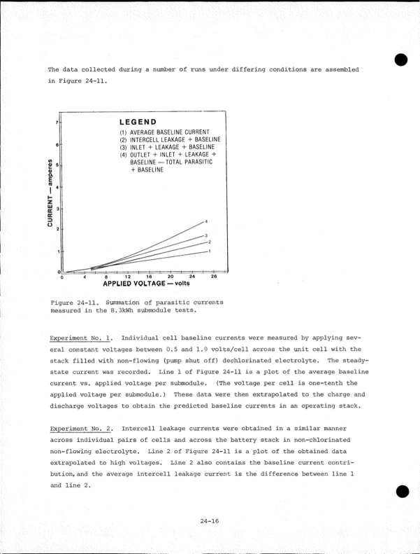
The data collected during a number of runs under differing conditions are assembled in Figure 24-11. LEGEND (1) AVERAGE BASELINE CURRENT (2) INTERCELL LEAKAGE + BASELINE (3) INLET + LEAKAGE + BASELINE (4) OUTLET + INLET + LEAKAGE + BASELINE — TOTAL PARASITIC + BASELINE APPLIED VOLTAGE —volts Figure 24-11. Summation of parasitic currents measured in the 8.3kWh submodule tests. Experiment No. 1. Individual cell baseline currents were measured by applying sev eral constant voltages between 0.5 and 1.9 volts/cell across the unit cell with the stack filled with non-flowing (pump shut off) dechlorinated electrolyte. The steady- state current was recorded. Line 1 of Figure 24-11 is a plot of the average baseline current vs. applied voltage per submodule. (The voltage per cell is one-tenth the applied voltage per submodule.) These data were then extrapolated to the charge and discharge voltages to obtain the predicted baseline currents in an operating stack. Experiment No. 2. Intercell leakage currents were obtained in a similar manner across individual pairs of cells and across the battery stack in non-chlorinated non-flowing electrolyte. Line 2 of Figure 24-11 is a plot of the obtained data extrapolated to high voltages. Line 2 also contains the baseline current contri bution, and the average intercell leakage current is the difference between line 1 and line 2. 24-16 CURRENT— amperPDF Image | Development of the Zinc-Chlorine Battery for Utility
PDF Search Title:
Development of the Zinc-Chlorine Battery for UtilityOriginal File Name Searched:
6302789.pdfDIY PDF Search: Google It | Yahoo | Bing
Salgenx Redox Flow Battery Technology: Power up your energy storage game with Salgenx Salt Water Battery. With its advanced technology, the flow battery provides reliable, scalable, and sustainable energy storage for utility-scale projects. Upgrade to a Salgenx flow battery today and take control of your energy future.
| CONTACT TEL: 608-238-6001 Email: greg@salgenx.com | RSS | AMP |