PDF Publication Title:
Text from PDF Page: 072
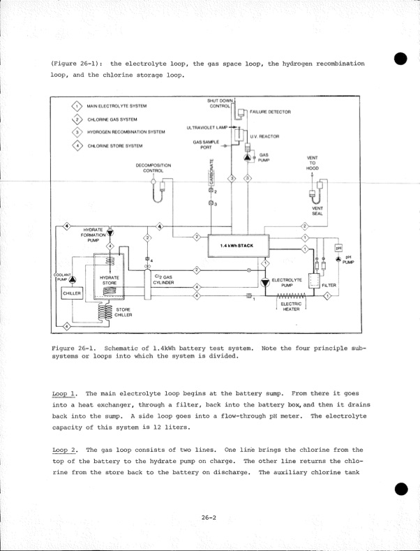
(Figure 26-1): the electrolyte loop, the gas space loop, the hydrogen recombination loop, and the chlorine storage loop. Figure 26-1. Schematic of 1.4kWh battery test system. Note the four principle sub systems or loops into which the system is divided. Loop 1. The main electrolyte loop begins at the battery sump. From there it goes into a heat exchanger, through a filter, back into the battery box, and then it drains back into the sump. A side loop goes into a flow-through pH meter. The electrolyte capacity of this system is 12 liters. Loop 2. The gas loop consists of two lines. One line brings the chlorine from the top of the battery to the hydrate pump on charge. The other line returns the chlo rine from the store back to the battery on discharge. The auxiliary chlorine tank 26-2PDF Image | Development of the Zinc-Chlorine Battery for Utility
PDF Search Title:
Development of the Zinc-Chlorine Battery for UtilityOriginal File Name Searched:
6302789.pdfDIY PDF Search: Google It | Yahoo | Bing
Salgenx Redox Flow Battery Technology: Power up your energy storage game with Salgenx Salt Water Battery. With its advanced technology, the flow battery provides reliable, scalable, and sustainable energy storage for utility-scale projects. Upgrade to a Salgenx flow battery today and take control of your energy future.
CONTACT TEL: 608-238-6001 Email: greg@salgenx.com (Standard Web Page)