PDF Publication Title:
Text from PDF Page: 004
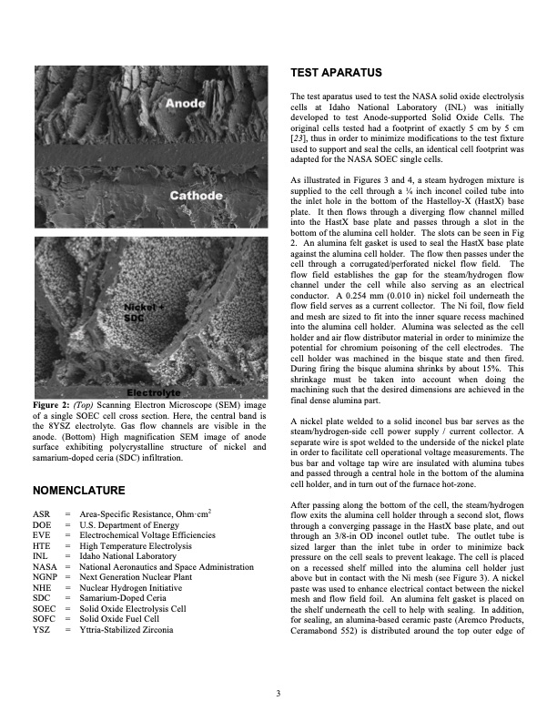
Figure 2: (Top) Scanning Electron Microscope (SEM) image of a single SOEC cell cross section. Here, the central band is the 8YSZ electrolyte. Gas flow channels are visible in the anode. (Bottom) High magnification SEM image of anode surface exhibiting polycrystalline structure of nickel and samarium-doped ceria (SDC) infiltration. NOMENCLATURE TEST APARATUS The test aparatus used to test the NASA solid oxide electrolysis cells at Idaho National Laboratory (INL) was initially developed to test Anode-supported Solid Oxide Cells. The original cells tested had a footprint of exactly 5 cm by 5 cm [23], thus in order to minimize modifications to the test fixture used to support and seal the cells, an identical cell footprint was adapted for the NASA SOEC single cells. As illustrated in Figures 3 and 4, a steam hydrogen mixture is supplied to the cell through a 1⁄4 inch inconel coiled tube into the inlet hole in the bottom of the Hastelloy-X (HastX) base plate. It then flows through a diverging flow channel milled into the HastX base plate and passes through a slot in the bottom of the alumina cell holder. The slots can be seen in Fig 2. An alumina felt gasket is used to seal the HastX base plate against the alumina cell holder. The flow then passes under the cell through a corrugated/perforated nickel flow field. The flow field establishes the gap for the steam/hydrogen flow channel under the cell while also serving as an electrical conductor. A 0.254 mm (0.010 in) nickel foil underneath the flow field serves as a current collector. The Ni foil, flow field and mesh are sized to fit into the inner square recess machined into the alumina cell holder. Alumina was selected as the cell holder and air flow distributor material in order to minimize the potential for chromium poisoning of the cell electrodes. The cell holder was machined in the bisque state and then fired. During firing the bisque alumina shrinks by about 15%. This shrinkage must be taken into account when doing the machining such that the desired dimensions are achieved in the final dense alumina part. A nickel plate welded to a solid inconel bus bar serves as the steam/hydrogen-side cell power supply / current collector. A separate wire is spot welded to the underside of the nickel plate in order to facilitate cell operational voltage measurements. The bus bar and voltage tap wire are insulated with alumina tubes and passed through a central hole in the bottom of the alumina cell holder, and in turn out of the furnace hot-zone. After passing along the bottom of the cell, the steam/hydrogen flow exits the alumina cell holder through a second slot, flows through a converging passage in the HastX base plate, and out through an 3/8-in OD inconel outlet tube. The outlet tube is sized larger than the inlet tube in order to minimize back pressure on the cell seals to prevent leakage. The cell is placed on a recessed shelf milled into the alumina cell holder just above but in contact with the Ni mesh (see Figure 3). A nickel paste was used to enhance electrical contact between the nickel mesh and flow field foil. An alumina felt gasket is placed on the shelf underneath the cell to help with sealing. In addition, for sealing, an alumina-based ceramic paste (Aremco Products, Ceramabond 552) is distributed around the top outer edge of ASR = DOE = EVE = HTE = INL = NASA = NGNP = NHE = SDC = SOEC = SOFC = YSZ = Area-Specific Resistance, Ohm·cm2 U.S. Department of Energy Electrochemical V oltage Efficiencies High Temperature Electrolysis Idaho National Laboratory National Aeronautics and Space Administration Next Generation Nuclear Plant Nuclear Hydrogen Initiative Samarium-Doped Ceria Solid Oxide Electrolysis Cell Solid Oxide Fuel Cell Yttria-Stabilized Zirconia 3PDF Image | Electrolysis Cells Operated Fuel Cell Steam Electrolysis
PDF Search Title:
Electrolysis Cells Operated Fuel Cell Steam ElectrolysisOriginal File Name Searched:
5223026.pdfDIY PDF Search: Google It | Yahoo | Bing
Salgenx Redox Flow Battery Technology: Power up your energy storage game with Salgenx Salt Water Battery. With its advanced technology, the flow battery provides reliable, scalable, and sustainable energy storage for utility-scale projects. Upgrade to a Salgenx flow battery today and take control of your energy future.
CONTACT TEL: 608-238-6001 Email: greg@salgenx.com (Standard Web Page)