PDF Publication Title:
Text from PDF Page: 005
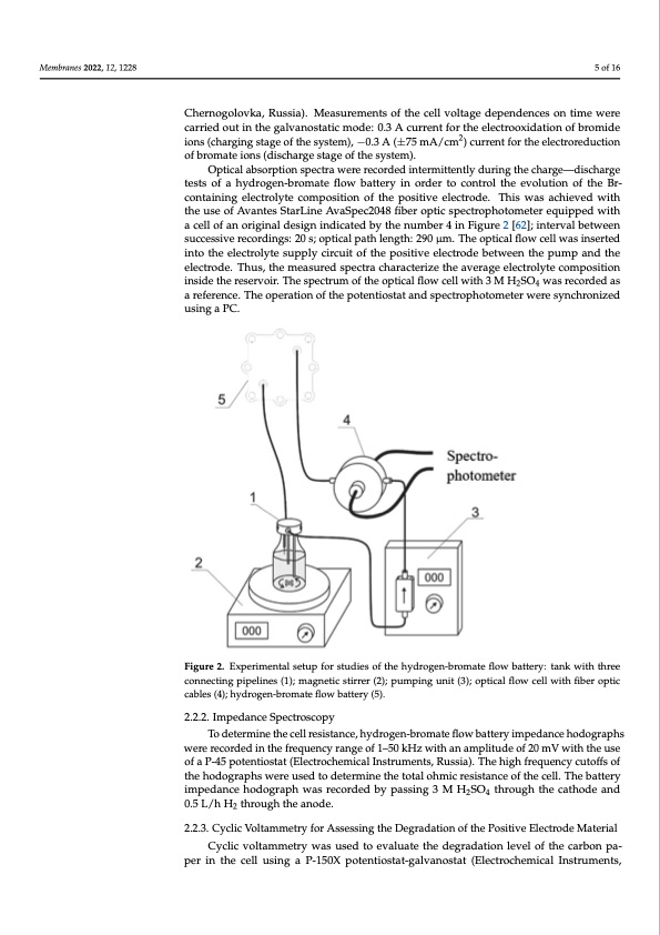
Membranes 2022, 12, x FOR PEER REVIEW 5 of 17 Membranes 2022, 12, 1228 2.2.1. Electrochemical Methods and Operando-Spectroscopic Control of the Catholyte Composition during Electrochemical Tests of the Hydrogen-Bromate Flow Battery 5 of 16 The charge—discharge characteristics of the hydrogen-bromate flow battery were measured using an Elins P-150X potentiostat-galvanostat (Electrochemical Instruments, Chernogolovka, Russia). Measurements of the cell voltage dependences on time were car- Chernogolovka, Russia). Measurements of the cell voltage dependences on time were ried out in the galvanostatic mode: 0.3 A current for the electrooxidation of bromide ions carried out in the galvanostatic mode: 0.3 A current for the electrooxidation of bromide (charging stage of the system), −0.3 A (±75 mA/cm2) cu2rrent for the electroreduction of ions (charging stage of the system), −0.3 A (±75 mA/cm ) current for the electroreduction bromate ions (discharge stage of the system). of bromate ions (discharge stage of the system). Optical absorption spectra were recorded intermittently during the charge—dis- Optical absorption spectra were recorded intermittently during the charge—discharge charge tests of a hydrogen-bromate flow battery in order to control the evolution of the tests of a hydrogen-bromate flow battery in order to control the evolution of the Br- Br-containing electrolyte composition of the positive electrode. This was achieved with containing electrolyte composition of the positive electrode. This was achieved with the use of Avantes StarLine AvaSpec2048 fiber optic spectrophotometer equipped with a the use of Avantes StarLine AvaSpec2048 fiber optic spectrophotometer equipped with cell of an original design indicated by the number 4 in Figure 2 [62]; interval between a cell of an original design indicated by the number 4 in Figure 2 [62]; interval between successive recordings: 20 s; optical path length: 290 μm. The optical flow cell was inserted successive recordings: 20 s; optical path length: 290 μm. The optical flow cell was inserted into the electrolyte supply circuit of the positive electrode between the pump and the elec- into the electrolyte supply circuit of the positive electrode between the pump and the trode. Thus, the measured spectra characterize the average electrolyte composition inside electrode. Thus, the measured spectra characterize the average electrolyte composition the reservoir. The spectrum of the optical flow cell with 3 M H2SO4 was recorded as a inside the reservoir. The spectrum of the optical flow cell with 3 M H2SO4 was recorded as arerfefrernecnec.eT.hTeheopopereartaitoinonooffththeepotteenttioiossttaattandspectrophotometerweresynchronized using a PC. Figure2.EExxppeerrimimeenntatallsesteutuppfofrosrtustduidesieosfothfetheydhryodgreong-ebnr-obmroamteaftleowflobwattbeartyt:etrayn:ktawnikthwthitrheethcorene- necting pipelines (1); magnetic stirrer (2); pumping unit (3); optical flow cell with fiber optic cables connecting pipelines (1); magnetic stirrer (2); pumping unit (3); optical flow cell with fiber optic (4); hydrogen-bromate flow battery (5). cables (4); hydrogen-bromate flow battery (5). 2.2.2. Impedance Spectroscopy 2.2.2. Impedance Spectroscopy To determine the cell resistance, hydrogen-bromate flow battery impedance hodographs To determine the cell resistance, hydrogen-bromate flow battery impedance hodo- were recorded in the frequency range of 1–50 kHz with an amplitude of 20 mV with the use graphs were recorded in the frequency range of 1–50 kHz with an amplitude of 20 mV of a P-45 potentiostat (Electrochemical Instruments, Russia). The high frequency cutoffs of with the use of a P-45 potentiostat (Electrochemical Instruments, Russia). The high fre- the hodographs were used to determine the total ohmic resistance of the cell. The battery quency cutoffs of the hodographs were used to determine the total ohmic resistance of the impedance hodograph was recorded by passing 3 M H2SO4 through the cathode and 0.5 L/h H2 through the anode. 2.2.3. Cyclic Voltammetry for Assessing the Degradation of the Positive Electrode Material Cyclic voltammetry was used to evaluate the degradation level of the carbon pa- per in the cell using a P-150X potentiostat-galvanostat (Electrochemical Instruments,PDF Image | Hydrogen-Bromate Flow Battery
PDF Search Title:
Hydrogen-Bromate Flow BatteryOriginal File Name Searched:
membranes-12-01228-v2.pdfDIY PDF Search: Google It | Yahoo | Bing
Salgenx Redox Flow Battery Technology: Power up your energy storage game with Salgenx Salt Water Battery. With its advanced technology, the flow battery provides reliable, scalable, and sustainable energy storage for utility-scale projects. Upgrade to a Salgenx flow battery today and take control of your energy future.
| CONTACT TEL: 608-238-6001 Email: greg@salgenx.com | RSS | AMP |