PDF Publication Title:
Text from PDF Page: 037
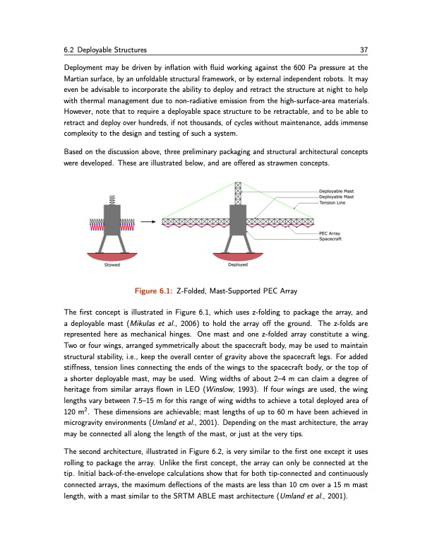
6.2 Deployable Structures 37 Deployment may be driven by inflation with fluid working against the 600 Pa pressure at the Martian surface, by an unfoldable structural framework, or by external independent robots. It may even be advisable to incorporate the ability to deploy and retract the structure at night to help with thermal management due to non-radiative emission from the high-surface-area materials. However, note that to require a deployable space structure to be retractable, and to be able to retract and deploy over hundreds, if not thousands, of cycles without maintenance, adds immense complexity to the design and testing of such a system. Based on the discussion above, three preliminary packaging and structural architectural concepts were developed. These are illustrated below, and are offered as strawmen concepts. Figure 6.1: Z-Folded, Mast-Supported PEC Array The first concept is illustrated in Figure 6.1, which uses z-folding to package the array, and a deployable mast (Mikulas et al., 2006) to hold the array off the ground. The z-folds are represented here as mechanical hinges. One mast and one z-folded array constitute a wing. Two or four wings, arranged symmetrically about the spacecraft body, may be used to maintain structural stability, i.e., keep the overall center of gravity above the spacecraft legs. For added stiffness, tension lines connecting the ends of the wings to the spacecraft body, or the top of a shorter deployable mast, may be used. Wing widths of about 2–4 m can claim a degree of heritage from similar arrays flown in LEO (Winslow, 1993). If four wings are used, the wing lengths vary between 7.5–15 m for this range of wing widths to achieve a total deployed area of 120 m2. These dimensions are achievable; mast lengths of up to 60 m have been achieved in microgravity environments (Umland et al., 2001). Depending on the mast architecture, the array may be connected all along the length of the mast, or just at the very tips. The second architecture, illustrated in Figure 6.2, is very similar to the first one except it uses rolling to package the array. Unlike the first concept, the array can only be connected at the tip. Initial back-of-the-envelope calculations show that for both tip-connected and continuously connected arrays, the maximum deflections of the masts are less than 10 cm over a 15 m mast length, with a mast similar to the SRTM ABLE mast architecture (Umland et al., 2001).PDF Image | ISRU Challenge Production of O2 and Fuel from CO2
PDF Search Title:
ISRU Challenge Production of O2 and Fuel from CO2Original File Name Searched:
ISRU_final_report.pdfDIY PDF Search: Google It | Yahoo | Bing
Salgenx Redox Flow Battery Technology: Power up your energy storage game with Salgenx Salt Water Battery. With its advanced technology, the flow battery provides reliable, scalable, and sustainable energy storage for utility-scale projects. Upgrade to a Salgenx flow battery today and take control of your energy future.
CONTACT TEL: 608-238-6001 Email: greg@salgenx.com (Standard Web Page)