PDF Publication Title:
Text from PDF Page: 038
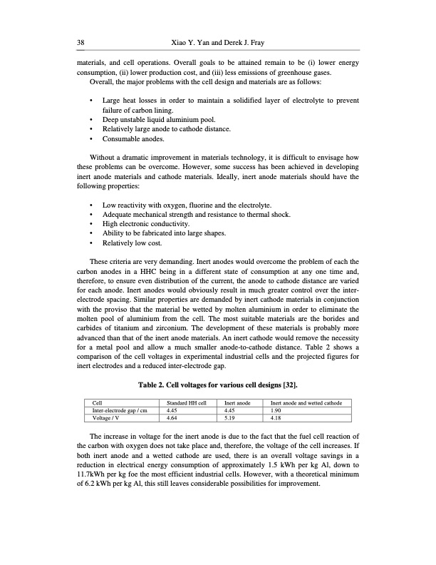
38 Xiao Y. Yan and Derek J. Fray materials, and cell operations. Overall goals to be attained remain to be (i) lower energy consumption, (ii) lower production cost, and (iii) less emissions of greenhouse gases. Overall, the major problems with the cell design and materials are as follows: • Large heat losses in order to maintain a solidified layer of electrolyte to prevent failure of carbon lining. • Deep unstable liquid aluminium pool. • Relatively large anode to cathode distance. • Consumable anodes. Without a dramatic improvement in materials technology, it is difficult to envisage how these problems can be overcome. However, some success has been achieved in developing inert anode materials and cathode materials. Ideally, inert anode materials should have the following properties: • Low reactivity with oxygen, fluorine and the electrolyte. • Adequate mechanical strength and resistance to thermal shock. • High electronic conductivity. • Ability to be fabricated into large shapes. • Relatively low cost. These criteria are very demanding. Inert anodes would overcome the problem of each the carbon anodes in a HHC being in a different state of consumption at any one time and, therefore, to ensure even distribution of the current, the anode to cathode distance are varied for each anode. Inert anodes would obviously result in much greater control over the inter- electrode spacing. Similar properties are demanded by inert cathode materials in conjunction with the proviso that the material be wetted by molten aluminium in order to eliminate the molten pool of aluminium from the cell. The most suitable materials are the borides and carbides of titanium and zirconium. The development of these materials is probably more advanced than that of the inert anode materials. An inert cathode would remove the necessity for a metal pool and allow a much smaller anode-to-cathode distance. Table 2 shows a comparison of the cell voltages in experimental industrial cells and the projected figures for inert electrodes and a reduced inter-electrode gap. Table 2. Cell voltages for various cell designs [32]. Cell Inter-electrode gap / cm Voltage / V Standard HH cell 4.45 4.64 Inert anode 4.45 5.19 Inert anode and wetted cathode 1.90 4.18 The increase in voltage for the inert anode is due to the fact that the fuel cell reaction of the carbon with oxygen does not take place and, therefore, the voltage of the cell increases. If both inert anode and a wetted cathode are used, there is an overall voltage savings in a reduction in electrical energy consumption of approximately 1.5 kWh per kg Al, down to 11.7kWh per kg foe the most efficient industrial cells. However, with a theoretical minimum of 6.2 kWh per kg Al, this still leaves considerable possibilities for improvement.PDF Image | MOLTEN SALT ELECTROLYSIS
PDF Search Title:
MOLTEN SALT ELECTROLYSISOriginal File Name Searched:
Molten-Salt-Electrolysis-Chapter-6.pdfDIY PDF Search: Google It | Yahoo | Bing
Salgenx Redox Flow Battery Technology: Power up your energy storage game with Salgenx Salt Water Battery. With its advanced technology, the flow battery provides reliable, scalable, and sustainable energy storage for utility-scale projects. Upgrade to a Salgenx flow battery today and take control of your energy future.
CONTACT TEL: 608-238-6001 Email: greg@salgenx.com (Standard Web Page)