PDF Publication Title:
Text from PDF Page: 003
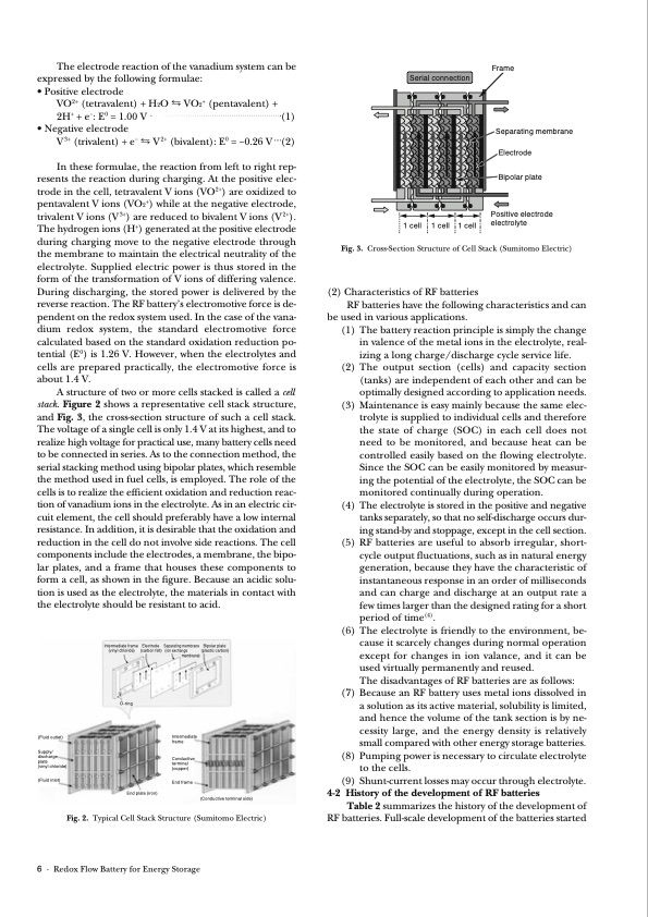
The electrode reaction of the vanadium system can be expressed by the following formulae: • Positive electrode VO2+ (tetravalent) + H2O ⇆ VO2+ (pentavalent) + 2H+ +e−:E0 =1.00V (1) • Negative electrode V3+ (trivalent) + e− ⇆ V2+ (bivalent): E0 = −0.26 V (2) In these formulae, the reaction from left to right rep- resents the reaction during charging. At the positive elec- trode in the cell, tetravalent V ions (VO2+) are oxidized to pentavalent V ions (VO2+) while at the negative electrode, trivalent V ions (V 3+) are reduced to bivalent V ions (V 2+). The hydrogen ions (H+) generated at the positive electrode during charging move to the negative electrode through the membrane to maintain the electrical neutrality of the electrolyte. Supplied electric power is thus stored in the form of the transformation of V ions of differing valence. During discharging, the stored power is delivered by the reverse reaction. The RF battery’s electromotive force is de- pendent on the redox system used. In the case of the vana- dium redox system, the standard electromotive force calculated based on the standard oxidation reduction po- tential (E0) is 1.26 V. However, when the electrolytes and cells are prepared practically, the electromotive force is about 1.4 V. A structure of two or more cells stacked is called a cell stack. Figure 2 shows a representative cell stack structure, and Fig. 3, the cross-section structure of such a cell stack. The voltage of a single cell is only 1.4 V at its highest, and to realize high voltage for practical use, many battery cells need to be connected in series. As to the connection method, the serial stacking method using bipolar plates, which resemble the method used in fuel cells, is employed. The role of the cells is to realize the efficient oxidation and reduction reac- tion of vanadium ions in the electrolyte. As in an electric cir- cuit element, the cell should preferably have a low internal resistance. In addition, it is desirable that the oxidation and reduction in the cell do not involve side reactions. The cell components include the electrodes, a membrane, the bipo- lar plates, and a frame that houses these components to form a cell, as shown in the figure. Because an acidic solu- tion is used as the electrolyte, the materials in contact with the electrolyte should be resistant to acid. Serial connection Frame Fig.2. TypicalCellStackStructure(SumitomoElectric) 6 · Redox Flow Battery for Energy Storage (Conductive terminal side) 1 cell 1 cell 1 cell Separating membrane Electrode Bipolar plate Positive electrode electrolyte (Fluid outlet) Supply/ discharge plate (vinyl chloride) (Fluid inlet) End frame End plate (iron) Intermediate frame (vinyl chloride) O-ring Electrode Separating membrane (carbon felt) (ion exchange membrane) Intermediate frame Conductive terminal (copper) Bipolar plate (plastic carbon) Fig. 3. Cross-Section Structure of Cell Stack (Sumitomo Electric) (2) Characteristics of RF batteries RF batteries have the following characteristics and can be used in various applications. (1) The battery reaction principle is simply the change in valence of the metal ions in the electrolyte, real- izing a long charge/discharge cycle service life. (2) The output section (cells) and capacity section (tanks) are independent of each other and can be optimally designed according to application needs. (3) Maintenance is easy mainly because the same elec- trolyte is supplied to individual cells and therefore the state of charge (SOC) in each cell does not need to be monitored, and because heat can be controlled easily based on the flowing electrolyte. Since the SOC can be easily monitored by measur- ing the potential of the electrolyte, the SOC can be monitored continually during operation. (4) The electrolyte is stored in the positive and negative tanks separately, so that no self-discharge occurs dur- ing stand-by and stoppage, except in the cell section. (5) RF batteries are useful to absorb irregular, short- cycle output fluctuations, such as in natural energy generation, because they have the characteristic of instantaneous response in an order of milliseconds and can charge and discharge at an output rate a few times larger than the designed rating for a short period of time(4). (6) The electrolyte is friendly to the environment, be- cause it scarcely changes during normal operation except for changes in ion valance, and it can be used virtually permanently and reused. The disadvantages of RF batteries are as follows: (7) Because an RF battery uses metal ions dissolved in a solution as its active material, solubility is limited, and hence the volume of the tank section is by ne- cessity large, and the energy density is relatively small compared with other energy storage batteries. (8) Pumping power is necessary to circulate electrolyte to the cells. (9) Shunt-current losses may occur through electrolyte. 4-2 History of the development of RF batteries Table 2 summarizes the history of the development of RFbatteries.Full-scaledevelopmentofthebatteriesstartedPDF Image | Redox Flow Battery for Energy Storage
PDF Search Title:
Redox Flow Battery for Energy StorageOriginal File Name Searched:
73-01.pdfDIY PDF Search: Google It | Yahoo | Bing
Salgenx Redox Flow Battery Technology: Power up your energy storage game with Salgenx Salt Water Battery. With its advanced technology, the flow battery provides reliable, scalable, and sustainable energy storage for utility-scale projects. Upgrade to a Salgenx flow battery today and take control of your energy future.
| CONTACT TEL: 608-238-6001 Email: greg@salgenx.com | RSS | AMP |