PDF Publication Title:
Text from PDF Page: 018
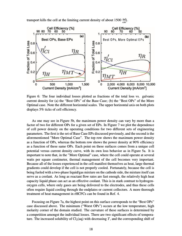
transport kills the cell at the limiting current density of about 1500 mA . cm2 Best OPs, More Optimal EPs Figure 6: The four individual losses plotted as fractions of the total loss vs. galvanic current density for (a) the “Best OPs” of the Base Case; (b) the “Best OPs” of the More Optimal case. Note the different horizontal scales. The upper horizontal axis on both plots displays 5% ticks of cell efficiency. As one may see in Figure 5b, the maximum power density can vary by more than a factor of two for different OPs for a given set of EPs. In Figure 7 we plot the dependence of cell power density on the operating conditions for two different sets of engineering parameters. The first is the set of Base Case EPs discussed previously, and the second is the aforementioned ”More Optimal Case”. The top row shows the maximum power density as a function of OPs, whereas the bottom row shows the power density at 90% efficiency as a function of these same OPs. Each point on these surfaces comes from a unique cell potential versus current density curve, with its own loss behavior as in Figure 5a. It is important to note that, in the ”More Optimal” case, where the cell could operate at several watts per square centimeter, thermal management of the cell becomes very important. Because all of the losses experienced in the cell manifest themselves as heat, large thermal gradients could develop if the cell is not properly cooled. Fortunately, because the cell is being fueled with a two-phase liquid/gas mixture on the cathode side, the mixture itself can serve as a coolant. As long as reactant flow rates are fast enough, the relatively high heat capacity liquid phase can act as an effective coolant. This is in stark contrast to hydrogen- oxygen cells, where only gases are being delivered to the electrodes, and thus these cells often require liquid cooling through the endplates or current collectors. A more thorough treatment of heat management in rHCFCs can be found in Ref. 4. Focusing on Figure 7a, the highest point on this surface corresponds to the “Best OPs” case discussed above. The minimum (“Worst OPs”) occurs at the low temperature, high molarity corner of the domain studied. The curvature of these surfaces is determined by a competition amongst the individual losses. There are two significant effects of tempera- ture. The increased solubility of Cl2(aq) with decreasing T, and the corresponding shift of 18PDF Image | Regenerative Hydrogen Chlorine Fuel Cell for Grid-Scale
PDF Search Title:
Regenerative Hydrogen Chlorine Fuel Cell for Grid-ScaleOriginal File Name Searched:
mja209.pdfDIY PDF Search: Google It | Yahoo | Bing
Salgenx Redox Flow Battery Technology: Power up your energy storage game with Salgenx Salt Water Battery. With its advanced technology, the flow battery provides reliable, scalable, and sustainable energy storage for utility-scale projects. Upgrade to a Salgenx flow battery today and take control of your energy future.
CONTACT TEL: 608-238-6001 Email: greg@salgenx.com (Standard Web Page)