PDF Publication Title:
Text from PDF Page: 009
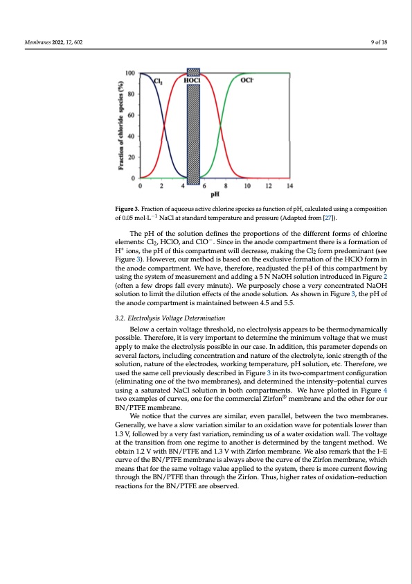
Membranes 2022, 11, x FOR PEER REVIEW 9 of 19 Membranes 2022, 12, 602 9 of 18 Figure 3. Fraction of aqueous active chlorine species as function of pH, calculated using a composition Figure 3. Fraction of aqueous active chlorine species as function of pH, calculated using a composi- of0.05mol·L−1N−a1Clatstandardtemperatureandpressure(Adaptedfrom[27]). tion of 0.05 mol·L NaCl at standard temperature and pressure (Adapted from [27]). The pH of the solution defines the proportions of the different forms of chlorine The pH of the solution defines the proportions of the different forms of chlorine ele- elements: Cl2, HClO, and ClO−. Since in the anode compartment there is a formation of men+ts: Cl2, HClO, and ClO−. Since in the anode compartment there is a formation of H+ H ions, the pH of this compartment will decrease, making the Cl2 form predominant (see ions, the pH of this compartment will decrease, making the Cl2 form predominant (see Figure 3). However, our method is based on the exclusive formation of the HClO form in Fitghueraen3o)d.eHcowmepvaertrm,oeuntr.mWethoavdei,sthbearseefodreo,nretahdejuesxtceldusthiveepfHoromfathtiosncoomfpthaertmHeCnltObyformin thuesianngotdhescyosmtempaorftmenastu.rWemeehnatvaned,tahdedrienfgorae5,rNeaNdajOusHtesdoluthtieonpHintroofdtuhciesdcionmFipgaurtem2entby (often a few drops fall every minute). We purposely chose a very concentrated NaOH using the system of measurement and adding a 5 N NaOH solution introduced in Figure solution to limit the dilution effects of the anode solution. As shown in Figure 3, the pH of 2 (often a few drops fall every minute). We purposely chose a very concentrated NaOH Below a certain voltage threshold, no electrolysis appears to be thermodynamically the anode compartment is maintained between 4.5 and 5.5. solution to limit the dilution effects of the anode solution. As shown in Figure 3, the pH of the anode compartment is maintained between 4.5 and 5.5. 3.2. Electrolysis Voltage Determination 3.2. Electrolysis Voltage Determination possible. Therefore, it is very important to determine the minimum voltage that we must apply to make the electrolysis possible in our case. In addition, this parameter depends on Below a certain voltage threshold, no electrolysis appears to be thermodynamically several factors, including concentration and nature of the electrolyte, ionic strength of the possible. Therefore, it is very important to determine the minimum voltage that we must solution, nature of the electrodes, working temperature, pH solution, etc. Therefore, we apply to make the electrolysis possible in our case. In addition, this parameter depends used the same cell previously described in Figure 3 in its two-compartment configuration on several factors, including concentration and nature of the electrolyte, ionic strength of (eliminating one of the two membranes), and determined the intensity–potential curves the solution, nature of the electrodes, working temperature, pH solution, etc. Therefore, using a saturated NaCl solution in both compartments. We have plotted in Figure 4 we used the same cell previously described in Figu®re 3 in its two-compartment configu- two examples of curves, one for the commercial Zirfon membrane and the other for our ration (eliminating one of the two membranes), and determined the intensity–potential BN/PTFE membrane. curvesWuesinogtiacestahtuatrathtedcuNravCeslasroelustimioinlairn, ebvoetnhpcaormalpleal,rtbmetewnetes.nWthehtwavoempelomttberdaniens.Figure Generally, we have a slow variation similar to an oxidation wave for potentials lower than 4 two examples of curves, one for the commercial Zirfon® membrane and the other for our 1.3 V, followed by a very fast variation, reminding us of a water oxidation wall. The voltage BN/PTFE membrane. at the transition from one regime to another is determined by the tangent method. We obtain 1.2 V with BN/PTFE and 1.3 V with Zirfon membrane. We also remark that the I–E curve of the BN/PTFE membrane is always above the curve of the Zirfon membrane, which means that for the same voltage value applied to the system, there is more current flowing through the BN/PTFE than through the Zirfon. Thus, higher rates of oxidation–reduction reactions for the BN/PTFE are observed.PDF Image | Zero Gap Electrolysis Cell for Producing Bleach
PDF Search Title:
Zero Gap Electrolysis Cell for Producing BleachOriginal File Name Searched:
membranes-12-00602.pdfDIY PDF Search: Google It | Yahoo | Bing
Salgenx Redox Flow Battery Technology: Power up your energy storage game with Salgenx Salt Water Battery. With its advanced technology, the flow battery provides reliable, scalable, and sustainable energy storage for utility-scale projects. Upgrade to a Salgenx flow battery today and take control of your energy future.
| CONTACT TEL: 608-238-6001 Email: greg@salgenx.com | RSS | AMP |