PDF Publication Title:
Text from PDF Page: 305
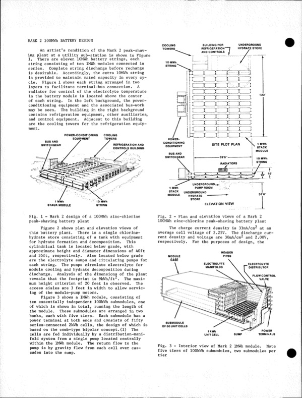
MARK 2 lOOMWh BATTERY DESIGN An artist's rendition of the Mark 2 peak-shav ing plant at a utility sub-station is shown in Figure 1. There are eleven lOMWh battery strings, each string consisting of ten IMWh modules connected in series. Completestringdischargebeforerecharge is desirable. Accordingly, the extra lOMWh string is provided to maintain rated capacity in every cy cle. Figure 1 shows each string arranged in two layers to facilitate terminal-bus connection. A radiator for control of the electrolyte temperature in the battery module is located above the center of each string. In the left background, the power conditioning equipment and the associated bus-work maybeseen. Thebuildingintherightbackground contains refrigeration equipment, other auxiliaries, and control equipment. Adjacent to this building are the cooling towers for the refrigeration equip ment . COOLING TOWERS. 10 MWh STRING BUILDING FOR REFRIGERATION AND CONTROLS UNDERGROUND HYDRATE STORE BUS AND SWITCHGEAR 1 MWh STACK MODULE REFRIGERATIONAND CONTROLS BUILDING SITEPLOTPLAN POWER-CONDITIONING EQUIPMENT COOLING TOWERS POWER- CONDITIONING EQUIPMENT BUS AND SWITCHGEAR 122' 1 MWh STACK MODULE 10 MWh STRING 38'6'' Fig. 1 - Mark 2 design of a lOOMWh zinc-chlorine peak-shaving battery plant Figure 2 shows plan and elevation views of this battery plant. There is a single chlorine- hydrate store consisting of a tank with equipment for hydrate formation and decomposition. This cylindrical tank is located below grade, with approximate height and diameter dimensions of 40ft and 35ft, respectively. Also located below grade are the electrolyte sumps and circulating pumps for each string. The pumps circulate electrolyte for module cooling and hydrate decomposition during discharge. Analysis of the dimensions of the plant reveals that the footprint is 9kWh/ft^. The maxi mum height criterion of 20 feet is observed. The access aisles are 3 feet in width to allow servic ing of the module-pump motors. Figure 3 shows a IMWh module, consisting of ten essentially independent lOOkWh submodules, one of which is shown in total, running the length of the module. These submodules are arranged in two banks,eachwithfivetiers. Eachsubmodulehasa power terminal at both ends and consists of fifty series-connected 2kWh cells, the design of which is basedonthecomb-typebipolarconcept.(1) The cells are fed individually by a distribution-mani fold system from a single pump located centrally within the IMWh module. The return flow to the pump is by gravity flow from each cell over cas cades into the sump. Fig. 2 - Plan and elevation views of a Mark 2 lOOMWh zinc-chlorine peak-shaving battery plant The charge current density is 33mA/cm2 at an average cell voltage of 2.25V. The discharge cur rent density and voltage are SOmA/cm^ and 2.00V, respectively. For the purposes of design, the 10 MWh STRING STORE 1 MWh STACK MODULE UNDERGROUND-^. PUMP ROOM UNDERGROUND HYDRATE ---------- - MODULE HEADER PIPES t-i.. ELEVATION VIEW RADIATORS UNIT CELL SUMP TERMINALS Fig. 3 - Interior view of Mark 2 IMWh module. Note five tiers of lOOkWh submodules, two submodules per tierPDF Image | Development of the Zinc-Chlorine Battery for Utility
PDF Search Title:
Development of the Zinc-Chlorine Battery for UtilityOriginal File Name Searched:
6302789.pdfDIY PDF Search: Google It | Yahoo | Bing
Salgenx Redox Flow Battery Technology: Power up your energy storage game with Salgenx Salt Water Battery. With its advanced technology, the flow battery provides reliable, scalable, and sustainable energy storage for utility-scale projects. Upgrade to a Salgenx flow battery today and take control of your energy future.
| CONTACT TEL: 608-238-6001 Email: greg@salgenx.com | RSS | AMP |