PDF Publication Title:
Text from PDF Page: 006
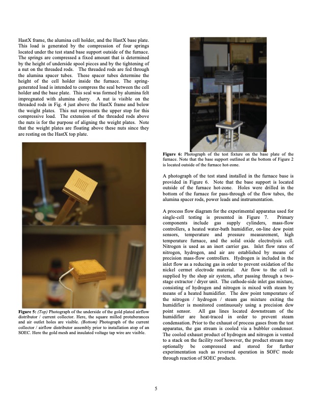
HastX frame, the alumina cell holder, and the HastX base plate. This load is generated by the compression of four springs located under the test stand base support outside of the furnace. The springs are compressed a fixed amount that is determined by the height of underside spool pieces and by the tightening of a nut on the threaded rods. The threaded rods are fed through the alumina spacer tubes. These spacer tubes determine the height of the cell holder inside the furnace. The spring- generated load is intended to compress the seal between the cell holder and the base plate. This seal was formed by alumina felt impregnated with alumina slurry. A nut is visible on the threaded rods in Fig. 4 just above the HastX frame and below the weight plates. This nut represents the upper stop for this compressive load. The extension of the threaded rods above the nuts is for the purpose of aligning the weight plates. Note that the weight plates are floating above these nuts since they are resting on the HastX top plate. Figure 5: (Top) Photograph of the underside of the gold plated airflow distributor / current collector. Here, the square milled protuberances and air outlet holes are visible. (Bottom) Photograph of the current collector / airflow distributor assembly prior to installation atop of an SOEC. Here the gold mesh and insulated voltage tap wire are visible. Figure 6: Photograph of the test fixture on the base plate of the furnace. Note that the base support outlined at the bottom of Figure 2 is located outside of the furnace hot-zone. A photograph of the test stand installed in the furnace base is provided in Figure 6. Note that the base support is located outside of the furnace hot-zone. Holes were drilled in the bottom of the furnace for pass-through of the flow tubes, the alumina spacer rods, power leads and instrumentation. A process flow diagram for the experimental apparatus used for single-cell testing is presented in Figure 7. Primary components include gas supply cylinders, mass-flow controllers, a heated water-bath humidifier, on-line dew point sensors, temperature and pressure measurement, high temperature furnace, and the solid oxide electrolysis cell. Nitrogen is used as an inert carrier gas. Inlet flow rates of nitrogen, hydrogen, and air are established by means of precision mass-flow controllers. Hydrogen is included in the inlet flow as a reducing gas in order to prevent oxidation of the nickel cermet electrode material. Air flow to the cell is supplied by the shop air system, after passing through a two- stage extractor / dryer unit. The cathode-side inlet gas mixture, consisting of hydrogen and nitrogen is mixed with steam by means of a heated humidifier. The dew point temperature of the nitrogen / hydrogen / steam gas mixture exiting the humidifier is monitored continuously using a precision dew point sensor. All gas lines located downstream of the humidifier are heat-traced in order to prevent steam condensation. Prior to the exhaust of process gases from the test apparatus, the gas stream is cooled via a bubbler condenser. The cooled exhaust product of hydrogen and nitrogen is vented to a stack on the facility roof however, the product stream may optionally be compressed and stored for further experimentation such as reversed operation in SOFC mode through reaction of SOEC products. 5PDF Image | Electrolysis Cells Operated Fuel Cell Steam Electrolysis
PDF Search Title:
Electrolysis Cells Operated Fuel Cell Steam ElectrolysisOriginal File Name Searched:
5223026.pdfDIY PDF Search: Google It | Yahoo | Bing
Salgenx Redox Flow Battery Technology: Power up your energy storage game with Salgenx Salt Water Battery. With its advanced technology, the flow battery provides reliable, scalable, and sustainable energy storage for utility-scale projects. Upgrade to a Salgenx flow battery today and take control of your energy future.
| CONTACT TEL: 608-238-6001 Email: greg@salgenx.com | RSS | AMP |