PDF Publication Title:
Text from PDF Page: 004
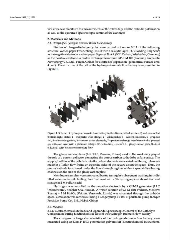
Membranes 2022, 12, 1228 4 of 16 Membranes 2022, 12, x FOR PEER REVIEW hydrogen-bromate MEA: Freidenberg H23C8 Pt-C/GP-IEM 103/Sigracet 39AA, H2SO4 with a surface area of 4 cm2. The completeness of the bromide to bromate co sion and vice versa was monitored via measurements of the cell voltage and the cat polarization as well as the operando-spectroscopic control of the catholyte. vice versa was monitored via measurements of the cell voltage and the cathodic polarization as well as the operando-spectroscopic control of the catholyte. 2. Materials and Methods 2. Materials and Methods 2.1. Design of a Hydrogen-Bromate Redox Flow Battery 2.1. Design of a Hydrogen-Bromate Redox Flow Battery Studies of charge-discharge cycles were carried out on an MEA of the foll Studies of charge-discharge cycles were carried out on an MEA of the following structure: carbon paper Freudenberg H23C8 with a catalytic layer (Pt/C loading 1 m structure: carbon paper Freudenberg H23C8 with a catalytic layer (Pt/C loading 1 mg/cm2) as the negative electrode, carbon paper Sigracet 39 AA (SGL Carbon, Wiesbaden as the negative electrode, carbon paper Sigracet 39 AA (SGL Carbon, Wiesbaden, Germany) many) as the positive electrode, a proton exchange membrane GP-IEM 103 (Lia as the positive electrode, a proton exchange membrane GP-IEM 103 (Liaoning Grepalofu Grepalofu NewEnergy Co., Ltd., Panjin, China) for electrodes’ separation (geom NewEnergy Co., Ltd., Panjin, China) for electrodes’ separation (geometrical surface area: 2 surface area: 4 cm2). The structure of the cell of the hydrogen-bromate flow battery i 4 cm ). The structure of the cell of the hydrogen-bromate flow battery is represented in Figure 1. resented in Figure 1. Figure 1. Scheme of hydrogen-bromate flow battery in the disassembled (centered) and assembled Figure 1. Scheme of hydrogen-bromate flow battery in the disassembled (centered) and asse (bottom right) states: 1—end plates with fittings; 2—Viton gasket, 3—current collectors, 4—graphite (bottom right) states: 1—end plates with fittings; 2—Viton gasket, 3—current collectors, 4—gr foil, 5—electrode gaskets, 6—carbon paper electrode, 7—proton-exchange membrane with a pressed foil, 5—electrode gaskets, 6—carbon paper electrode, 7—proton-exchange membrane 2 gas diffusion layperreswseitdhgaapsldatiifnfusmioncaltaylyesrtw(Pith/Ca lpoladtiinugm1 gca/tcamlys)t, (8P—t/gClalossaydicnagrb1ong/pcmlate),(8L—LCglEaslsy carbo 6, Russia) with h(LoLleCs Efolr6e,lRecutsrsoilay)tewflitohwh.oles for electrolyte flow. The glassy carbon plates (LLC El 6, Moscow, Russia) used in the work only played The glassy carbon plates (LLC El 6, Moscow, Russia) used in the work only p the role of a current collector, contacting the porous carbon cathode by a flat surface. The the role of a current collector, contacting the porous carbon cathode by a flat surfac supply/outflow of the catholyte into the carbon electrode was carried out through channels supply/outflow of the catholyte into the carbon electrode was carried out through made in a Teflon flow frame on opposite sides of the square electrode space. Thus, the nels made in a Teflon flow frame on opposite sides of the square electrode space. porous cathode functioned under the flow-through regime, without special distributing the porous cathode functioned under the flow-through regime, without special d channels on the side of the glassy carbon plate. uting channels on the side of the glassy carbon plate. Membrane samples were pretreated before testing by subsequent washing in tridis- Membrane samples were pretreated before testing by subsequent washi tilled water under mild boiling, then treatment with a 3% hydrogen peroxide solution and storage in 2 M sulfuric acid. tridistilled water under mild boiling, then treatment with a 3% hydrogen peroxide tion and storage in 2 M sulfuric acid. Hydrogen was supplied to the negative electrode by a GH-25 generator (LLC Hydrogen was supplied to the negative electrode by a GH-25 generator (LLC “Metachrom”, Yoshkar-Ola, Russia). A water solution of 0.3 M HBr (Vekton, Moscow, achrom”, Yoshkar-Ola, Russia). A water solution of 0.3 M HBr (Vekton, Moscow, R Russia) + 3 M H2SO4 (Vekton, Voronezh, Russia) was circulated through the cathode + 3 M H2SO4 (Vekton, Voronezh, Russia) was circulated through the cathode spac space. Circulation was carried out using a Longerpump BT-100-1f peristaltic pump (Longer culation was carried out using a Longerpump BT-100-1f peristaltic pump (Longer Precision Pump Co., Ltd., Hebei, China). sion Pump Co., Ltd. Hebei, China). 2.2. Methods 2.2. Methods 2.2.1. Electrochemical Methods and Operando-Spectroscopic Control of the Catholyte Composition during Electrochemical Tests of the Hydrogen-Bromate Flow Battery The charge—discharge characteristics of the hydrogen-bromate flow battery were measured using an Elins P-150X potentiostat-galvanostat (Electrochemical Instruments, 2 4 H o g , o e m w n e i n “ u e PPDF Image | Hydrogen-Bromate Flow Battery
PDF Search Title:
Hydrogen-Bromate Flow BatteryOriginal File Name Searched:
membranes-12-01228-v2.pdfDIY PDF Search: Google It | Yahoo | Bing
Salgenx Redox Flow Battery Technology: Power up your energy storage game with Salgenx Salt Water Battery. With its advanced technology, the flow battery provides reliable, scalable, and sustainable energy storage for utility-scale projects. Upgrade to a Salgenx flow battery today and take control of your energy future.
CONTACT TEL: 608-238-6001 Email: greg@salgenx.com (Standard Web Page)