PDF Publication Title:
Text from PDF Page: 006
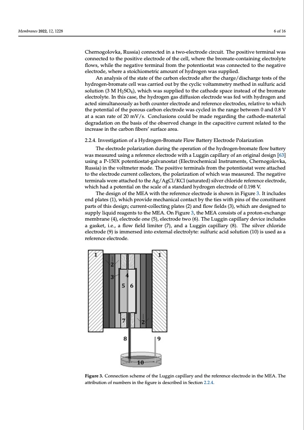
Membranes 2022, 12, 1228 6 of 16 Chernogolovka, Russia) connected in a two-electrode circuit. The positive terminal was connected to the positive electrode of the cell, where the bromate-containing electrolyte flows, while the negative terminal from the potentiostat was connected to the negative electrode, where a stoichiometric amount of hydrogen was supplied. An analysis of the state of the carbon electrode after the charge/discharge tests of the hydrogen-bromate cell was carried out by the cyclic voltammetry method in sulfuric acid solution (3 M H2SO4), which was supplied to the cathode space instead of the bromate electrolyte. In this case, the hydrogen gas diffusion electrode was fed with hydrogen and acted simultaneously as both counter electrode and reference electrodes, relative to which the potential of the porous carbon electrode was cycled in the range between 0 and 0.8 V at a scan rate of 20 mV/s. Conclusions could be made regarding the cathode-material degradation on the basis of the observed change in the capacitive current related to the increase in the carbon fibers’ surface area. 2.2.4. Investigation of a Hydrogen-Bromate Flow Battery Electrode Polarization The electrode polarization during the operation of the hydrogen-bromate flow battery was measured using a reference electrode with a Luggin capillary of an original design [63] using a P-150X potentiostat-galvanostat (Electrochemical Instruments, Chernogolovka, Russia) in the voltmeter mode. The positive terminals from the potentiostat were attached to the electrode current collectors, the polarization of which was measured. The negative terminals were attached to the Ag/AgCl/KCl (saturated) silver chloride reference electrode, which had a potential on the scale of a standard hydrogen electrode of 0.198 V. The design of the MEA with the reference electrode is shown in Figure 3. It includes end plates (1), which provide mechanical contact by the ties with pins of the constituent parts of this design; current-collecting plates (2) and flow fields (3), which are designed to supply liquid reagents to the MEA. On Figure 3, the MEA consists of a proton-exchange membrane (4), electrode one (5), electrode two (6). The Luggin capillary device includes a gasket, i.e., a flow field limiter (7), and a Luggin capillary (8). The silver chloride Membranes 2022, 12, x FOR PEER REVIEW 7 of 17 electrode (9) is immersed into external electrolyte: sulfuric acid solution (10) is used as a reference electrode. Figure 3.. Connection scheme of the Luggin capillary and the reference electrode in the MEA. The attribution of numbers in the figure is described in Section 2.2.4. attribution of numbers in the figure is described in Section 2.2.4. The silver chloride electrode was of a conventional construction: small reservoir filled by saturated KCl solution, into which silver wire coated with a layer of silver chloride was immersed. The reservoir possessed a liquid contact (through a frit made of porous sin- tered glass) with sulfuric acid solution, into which the end of the Luggin membrane capil- lary was also immersed, according to the diagram in Figure 3. The Luggin thin-film capillary was a strip of the Nafion-211 proton-exchange mem-PDF Image | Hydrogen-Bromate Flow Battery
PDF Search Title:
Hydrogen-Bromate Flow BatteryOriginal File Name Searched:
membranes-12-01228-v2.pdfDIY PDF Search: Google It | Yahoo | Bing
Salgenx Redox Flow Battery Technology: Power up your energy storage game with Salgenx Salt Water Battery. With its advanced technology, the flow battery provides reliable, scalable, and sustainable energy storage for utility-scale projects. Upgrade to a Salgenx flow battery today and take control of your energy future.
CONTACT TEL: 608-238-6001 Email: greg@salgenx.com (Standard Web Page)