PDF Publication Title:
Text from PDF Page: 008
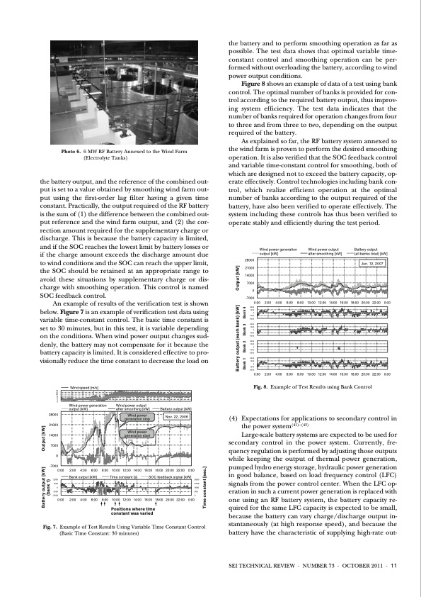
Photo 6. 6 MW RF Battery Annexed to the Wind Farm (Electrolyte Tanks) the battery output, and the reference of the combined out- put is set to a value obtained by smoothing wind farm out- put using the first-order lag filter having a given time constant. Practically, the output required of the RF battery is the sum of (1) the difference between the combined out- put reference and the wind farm output, and (2) the cor- rection amount required for the supplementary charge or discharge. This is because the battery capacity is limited, and if the SOC reaches the lowest limit by battery losses or if the charge amount exceeds the discharge amount due to wind conditions and the SOC can reach the upper limit, the SOC should be retained at an appropriate range to avoid these situations by supplementary charge or dis- charge with smoothing operation. This control is named SOC feedback control. An example of results of the verification test is shown below. Figure 7 is an example of verification test data using variable time-constant control. The basic time constant is set to 30 minutes, but in this test, it is variable depending on the conditions. When wind power output changes sud- denly, the battery may not compensate for it because the battery capacity is limited. It is considered effective to pro- visionally reduce the time constant to decrease the load on the battery and to perform smoothing operation as far as possible. The test data shows that optimal variable time- constant control and smoothing operation can be per- formed without overloading the battery, according to wind power output conditions. Figure 8 shows an example of data of a test using bank control. The optimal number of banks is provided for con- trol according to the required battery output, thus improv- ing system efficiency. The test data indicates that the number of banks required for operation changes from four to three and from three to two, depending on the output required of the battery. As explained so far, the RF battery system annexed to the wind farm is proven to perform the desired smoothing operation. It is also verified that the SOC feedback control and variable time-constant control for smoothing, both of which are designed not to exceed the battery capacity, op- erate effectively. Control technologies including bank con- trol, which realize efficient operation at the optimal number of banks according to the output required of the battery, have also been verified to operate effectively. The system including these controls has thus been verified to operate stably and efficiently during the test period. 30 25 20 15 10 5 0 28000 21000 14000 7000 0 -7000 Wind speed [m/s] Wind power generation output [kW] Wind power output after smoothing [kW] Wind power generation stop Wind power generation start Battery output [kW] Nov. 22, 2006 0:00 2:00 4:00 6:00 8:00 10:00 12:00 14:00 16:00 18:00 20:00 22:00 0:00 2000 1000 0 -1000 -2000 2000 1000 0 -1000 -2000 2000 1000 0 -1000 -2000 2000 1000 0 -1000 -2000 0:00 2:00 4:00 6:00 8:00 10:00 12:00 14:00 16:00 18:00 20:00 22:00 0:00 Fig. 8. Example of Test Results using Bank Control (4) Expectations for applications to secondary control in the power system(41)–(43) Large-scale battery systems are expected to be used for secondary control in the power system. Currently, fre- quency regulation is performed by adjusting those outputs while keeping the output of thermal power generation, pumped hydro energy storage, hydraulic power generation in good balance, based on load frequency control (LFC) signals from the power control center. When the LFC op- eration in such a current power generation is replaced with one using an RF battery system, the battery capacity re- quired for the same LFC capacity is expected to be small, because the battery can vary charge/discharge output in- stantaneously (at high response speed), and because the battery have the characteristic of supplying high-rate out- 0:00 2:00 4:00 6:00 8:00 10:00 12:00 14:00 16:00 18:00 20:00 22:00 0:00 2000 Bank output [kW] 1000 0 -1000 -2000 Time constant [s] SOC feedback signal [kW] 3600 2700 1800 900 0 0:00 2:00 4:00 6:00 8:00 10:00 12:00 14:00 16:00 18:00 20:00 22:00 0:00 Positions where time constant was varied Fig. 7. Example of Test Results Using Variable Time Constant Control (Basic Time Constant: 30 minutes) 28000 21000 14000 7000 0 -7000 Wind power generation output [kW] Wind power output after smoothing [kW] Battery output (all banks total) [kW] Jun. 12, 2007 Battery output [kW] Output [kW] (bank 1) Time constant [sec.] Battery output (each bank) [kW] Output [kW] Bank 1 Bank 2 Bank 3 Bank 4 SEI TECHNICAL REVIEW · NUMBER 73 · OCTOBER 2011 · 11PDF Image | Redox Flow Battery for Energy Storage
PDF Search Title:
Redox Flow Battery for Energy StorageOriginal File Name Searched:
73-01.pdfDIY PDF Search: Google It | Yahoo | Bing
Salgenx Redox Flow Battery Technology: Power up your energy storage game with Salgenx Salt Water Battery. With its advanced technology, the flow battery provides reliable, scalable, and sustainable energy storage for utility-scale projects. Upgrade to a Salgenx flow battery today and take control of your energy future.
CONTACT TEL: 608-238-6001 Email: greg@salgenx.com (Standard Web Page)