PDF Publication Title:
Text from PDF Page: 308
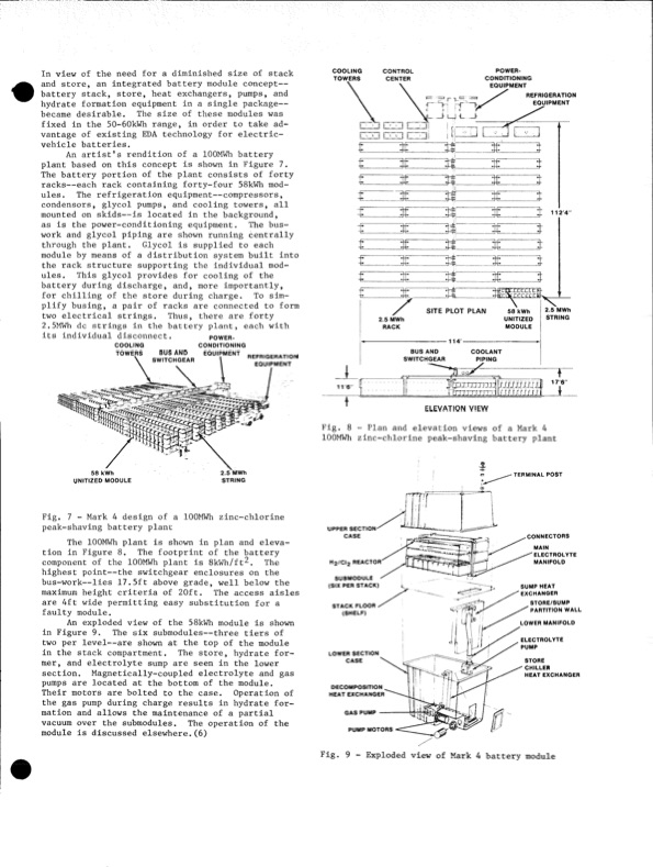
In view of the need for a diminished size of stack and store, an integrated battery module concept— battery stack, store, heat exchangers, pumps, and hydrate formation equipment in a single package— became desirable. The size of these modules was fixed in the 50-60kWh range, in order to take ad vantage of existing EDA technology for electric- vehicle batteries. An artist’s rendition of a lOOMWh battery plant based on this concept is shown in Figure 7. The battery portion of the plant consists of forty racks— each rack containing forty-four 58kWh mod ules. The refrigeration equipment—compressors, condensers, glycol pumps, and cooling towers, all mounted on skids—is located in the background, as is the power-conditioning equipment. The bus- work and glycol piping are shown running centrally through the plant. Glycol is supplied to each module by means of a distribution system built into the rack structure supporting the individual mod ules. This glycol provides for cooling of the battery during discharge, and, more importantly, for chilling of the store during charge. To sim plify busing, a pair of racks are connected to form two electrical strings. Thus, there are forty 2.5MWh dc strings in the battery plant, each with COOLING TOWERS CONTROL CENTER POWER- CONDITIONING EQUIPMENT its individual disconnect. power CONDITIONING EQUIPMENT 2.5 MWh STRING cooling TOWERS 58 kWh UNITIZED MODULE BUS AND SWITCHGEAR REFRIGERATION EQUIPMENT COOLANT PIPING 2.5 MWh RACK BUS AND SWITCHGEAR 58 kWh UNITIZED MODULE SITE PLOT PLAN REFRIGERATION EQUIPMENT J 1124 2.5 MWh STRING Fig. 7 - Mark 4 design of a lOOMWh zinc-chlorine peak-shaving battery plant The lOOMWh plant is shown in plan and eleva tioninFigure8. Thefootprintofthebattery component of the lOOMWh plant is SkWh/ft^. The highest point—the switchgear enclosures on the bus-work—lies 17.5ft above grade, well below the maximum height criteria of 20ft. The access aisles are 4ft wide permitting easy substitution for a faulty module. An exploded view of the 58kWh module is shown in Figure 9. The six submodules—three tiers of two per level— are shown at the top of the module in the stack compartment. The store, hydrate for mer, and electrolyte sump are seen in the lower section. Magnetically-coupled electrolyte and gas pumps are located at the bottom of the module. Their motors are bolted to the case. Operation of the gas pump during charge results in hydrate for mation and allows the maintenance of a partial vacuum over the submodules. The operation of the module is discussed elsewhere.(6) UPPER SECTION CASE H2/CI2 REACTOR’ SUBMODULE (SIX PER STACK) STACK FLOOR (SHELF) LOWER SECTION CASE DECOMPOSITION . HEAT EXCHANGER GAS PUMP PUMP MOTORS TERMINAL POST CONNECTORS MAIN ELECTROLYTE MANIFOLD SUMP HEAT EXCHANGER STORE/SUMP ^ PARTITION WALL LOWER MANIFOLD ELECTROLYTE PUMP STORE CHILLER HEAT EXCHANGER 116" ELEVATION VIEW Fig. 8 - Plan and elevation views of a Mark 4 lOOMWh zinc-chlorine peak-shaving battery plant Fig. 9 - Exploded view of Mark 4 battery modulePDF Image | Development of the Zinc-Chlorine Battery for Utility
PDF Search Title:
Development of the Zinc-Chlorine Battery for UtilityOriginal File Name Searched:
6302789.pdfDIY PDF Search: Google It | Yahoo | Bing
Salgenx Redox Flow Battery Technology: Power up your energy storage game with Salgenx Salt Water Battery. With its advanced technology, the flow battery provides reliable, scalable, and sustainable energy storage for utility-scale projects. Upgrade to a Salgenx flow battery today and take control of your energy future.
| CONTACT TEL: 608-238-6001 Email: greg@salgenx.com | RSS | AMP |