PDF Publication Title:
Text from PDF Page: 010
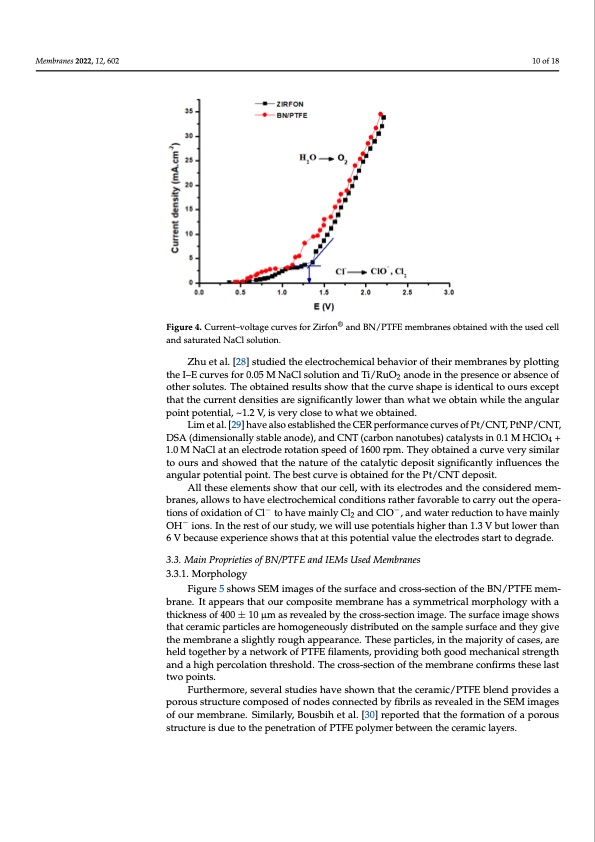
Membranes 2022, 11, x FOR PEER REVIEW 10 of 19 Membranes 2022, 12, 602 10 of 18 ®® Figure 4.. Currreennt–t–vvooltlatgaegecucruvrevsefsorfoZrirZfoirnfonandanBdNB/NPT/PFTEFmEemebmranberasnoebstaoinbetadinweidthwthiethutsheed ucesleld cell theI–Ecurvesfor0.05MNaClsolutionandTi/RuO anodeinthepresenceorabsenceof Generally, we have a slow variation similar to an o2xidation wave for potentials lower than and saturated NaCl solution. and saturated NaCl solution. Zhu et al. [28] studied the electrochemical behavior of their membranes by plotting We notice that the curves are similar, even parallel, between the two membranes. other solutes. The obtained results show that the curve shape is identical to ours except 1.3 V, followed by a very fast variation, reminding us of a water oxidation wall. The volt- that the current densities are significantly lower than what we obtain while the angular age at the transition from one regime to another is determined by the tangent method. We point potential, ~1.2 V, is very close to what we obtained. obtain 1.2 V with BN/PTFE and 1.3 V with Zirfon membrane. We also remark that the I–E Lim et al. [29] have also established the CER performance curves of Pt/CNT, PtNP/CNT, curve of the BN/PTFE membrane is always above the curve of the Zirfon membrane, DSA (dimensionally stable anode), and CNT (carbon nanotubes) catalysts in 0.1 M HClO4 + which means that for the same voltage value applied to the system, there is more current 1.0 M NaCl at an electrode rotation speed of 1600 rpm. They obtained a curve very similar flowing through the BN/PTFE than through the Zirfon. Thus, higher rates of oxidation– to ours and showed that the nature of the catalytic deposit significantly influences the reduction reactions for the BN/PTFE are observed. angular potential point. The best curve is obtained for the Pt/CNT deposit. Zhu et al. [28] studied the electrochemical behavior of their membranes by plotting All these elements show that our cell, with its electrodes and the considered mem- tbhreanI–esE, aclulorvwestfoohra0v.0e5elMectNroacChlemsoilcuatlicoonnadnitdioTnis/RrauthOe2rafnavoodreabinletthoecparreyseonuctethoer oapbesrean-ce of −− otitohnesrosfolxuitdeast.ioTnhoefoCbltaitnoehdavresmualtisnlsyhColw2 atnhdatCtlhOe c, uanrvdewsahtearpreedisuicdtieonttiocahlatvoeomuarisnleyxcept OH− ions. In the rest of our study, we will use potentials higher than 1.3 V but lower than that the current densities are significantly lower than what we obtain while the angular 6 V because experience shows that at this potential value the electrodes start to degrade. point potential, ~1.2 V, is very close to what we obtained. Lim et al. [29] have also established the CER performance curves of Pt/CNT, 3.3. Main Proprieties of BN/PTFE and IEMs Used Membranes PtNP/CNT, DSA (dimensionally stable anode), and CNT (carbon nanotubes) catalysts in 3.3.1. Morphology 0.1 M HClO4 + 1.0 M NaCl at an electrode rotation speed of 1600 rpm. They obtained a Figure 5 shows SEM images of the surface and cross-section of the BN/PTFE mem- curve very similar to ours and showed that the nature of the catalytic deposit significantly brane. It appears that our composite membrane has a symmetrical morphology with a influences the angular potential point. The best curve is obtained for the Pt/CNT deposit. thickness of 400 ± 10 μm as revealed by the cross-section image. The surface image shows All these elements show that our cell, with its electrodes and the considered mem- that ceramic particles are homogeneously distributed on the sample surface and they give branes, allows to have electrochemical conditions rather favorable to carry out the opera- the membrane a slightly rough appearance. These particles, in the majority of cases, are tions of oxidation of Cl− to have mainly Cl2 and ClO−, and water reduction to have mainly held together by a network of PTFE filaments, providing both good mechanical strength OH− ions. In the rest of our study, we will use potentials higher than 1.3 V but lower than and a high percolation threshold. The cross-section of the membrane confirms these last 6twVobpeocianuts.e experience shows that at this potential value the electrodes start to degrade. Furthermore, several studies have shown that the ceramic/PTFE blend provides a 3p.o3r.oMusaisntrPurcotpurieetcioesmopfoBsNed/PoTfFnEodanesdcIoEnMnsecUtesdedbMy fiembrbirlsanaessrevealed in the SEM images of our membrane. Similarly, Bousbih et al. [30] reported that the formation of a porous 3.3.1. Morphology structure is due to the penetration of PTFE polymer between the ceramic layers. Figure 5 shows SEM images of the surface and cross-section of the BN/PTFE mem- brane. It appears that our composite membrane has a symmetrical morphology with a thickness of 400 ± 10 μm as revealed by the cross-section image. The surface image shows that ceramic particles are homogeneously distributed on the sample surface and they give the membrane a slightly rough appearance. These particles, in the majority of cases, are held together by a network of PTFE filaments, providing both good mechanical strengthPDF Image | Zero Gap Electrolysis Cell for Producing Bleach
PDF Search Title:
Zero Gap Electrolysis Cell for Producing BleachOriginal File Name Searched:
membranes-12-00602.pdfDIY PDF Search: Google It | Yahoo | Bing
Salgenx Redox Flow Battery Technology: Power up your energy storage game with Salgenx Salt Water Battery. With its advanced technology, the flow battery provides reliable, scalable, and sustainable energy storage for utility-scale projects. Upgrade to a Salgenx flow battery today and take control of your energy future.
CONTACT TEL: 608-238-6001 Email: greg@salgenx.com (Standard Web Page)